zener diode test

test schematic setup

test schematic
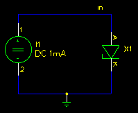
There are only two test simulations for a zener diode:
  1. the forward voltage
  2. the reverse voltage
Both simulations are done at different temperatures and plotted in two semilogy plots.

postprocessing tests

The expected range for the forward voltage should lay between 0 and 2.0 volts. It will catch all pinswap errors in the part definitions.

The expected range for the reverse voltage should be between 0 and 200 volts. Even if this range looks stupid, it will catch all model errors where either the reverse voltage is not specified or the simulator takes a standard diode because of various model errors.

example test results

IF voltage graph
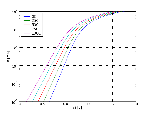
forward current as a function of forward voltage at different temperatures.
UR voltage graph
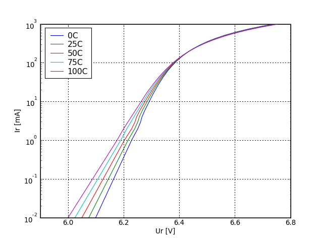
Reverse current as a function of reverse voltage at different temperatures.

Werner Hoch
Last modified: Sat Dec 29 18:22:34 CET 2007